- 您现在的位置:买卖IC网 > Sheet目录3882 > PIC18F4539T-I/ML (Microchip Technology)IC MCU FLASH 12KX16 EE A/D 44QFN
PIC18FXX39
DS30485A-page 186
Preliminary
2002 Microchip Technology Inc.
18.2
Selecting the A/D Conversion Clock
The A/D conversion time per bit is defined as TAD. The
A/D conversion requires 12 TAD per 10-bit conversion.
The source of the A/D conversion clock is software
selectable. The seven possible options for TAD are:
2 TOSC
4 TOSC
8 TOSC
16 TOSC
32 TOSC
64 TOSC
Internal A/D module RC oscillator (2-6
s)
For correct A/D conversions, the A/D conversion clock
(TAD) must be selected to ensure a minimum TAD time
of 1.6
s.
the device operating frequencies and the A/D clock
source selected.
18.3
Configuring Analog Port Pins
The ADCON1, TRISA and TRISE registers control the
operation of the A/D port pins. The port pins, that are
desired as analog inputs, must have their corresponding
TRIS bits set (input). If the TRIS bit is cleared (output),
the digital output level (VOH or VOL) will be converted.
The A/D operation is independent of the state of the
CHS2:CHS0 bits and the TRIS bits.
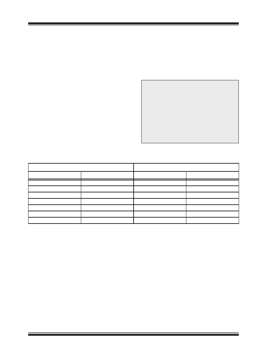
TABLE 18-1:
TAD vs. DEVICE OPERATING FREQUENCIES
Note 1: When reading the port register, all pins
configured as analog input channels will
read as cleared (a low level). Pins config-
ured as digital inputs will convert an analog
input. Analog levels on a digitally config-
ured input will not affect the conversion
accuracy.
2: Analog levels on any pin that is defined as
a digital input (including the AN4:AN0
pins) may cause the input buffer to con-
sume current that is out of the device’s
specification.
AD Clock Source (TAD)
Maximum Device Frequency
Operation
ADCS2:ADCS0
PIC18FXX39
PIC18LFXX39
2 TOSC
000
1.25 MHz
666 kHz
4 TOSC
100
2.50 MHz
1.33 MHz
8 TOSC
001
5.00 MHz
2.67 MHz
16 TOSC
101
10.00 MHz
5.33 MHz
32 TOSC
010
20.00 MHz
10.67 MHz
64 TOSC
110
40.00 MHz
21.33 MHz
RC
011
——
发布紧急采购,3分钟左右您将得到回复。
相关PDF资料
PIC18LF2539T-I/SO
IC MCU FLASH 12KX16 EE AD 28SOIC
PIC18LF4539T-I/PT
IC MCU FLASH 12KX16 EE AD 44TQFP
PIC16LF874AT-I/ML
IC MCU FLASH 4KX14 A/D 44QFN
PIC16F77T-E/ML
IC MCU FLASH 8KX14 A/D 44QFN
PIC16F874A-E/ML
IC MCU FLASH 4KX14 A/D 44QFN
PIC16F74T-I/ML
IC MCU FLASH 4KX14 A/D 44QFN
PIC16F77T-I/ML
IC MCU FLASH 8KX14 A/D 44QFN
PIC18F24K20-I/SS
IC PIC MCU FLASH 8KX16 28SSOP
相关代理商/技术参数
PIC18F4539T-I/PT
功能描述:8位微控制器 -MCU 24KB 1408 RAM 32 I/O RoHS:否 制造商:Silicon Labs 核心:8051 处理器系列:C8051F39x 数据总线宽度:8 bit 最大时钟频率:50 MHz 程序存储器大小:16 KB 数据 RAM 大小:1 KB 片上 ADC:Yes 工作电源电压:1.8 V to 3.6 V 工作温度范围:- 40 C to + 105 C 封装 / 箱体:QFN-20 安装风格:SMD/SMT
PIC18F4550EPT
制造商:Microchip Technology Inc 功能描述:
PIC18F4550-I/ML
功能描述:8位微控制器 -MCU 32kBF 2048RM FSUSB2 RoHS:否 制造商:Silicon Labs 核心:8051 处理器系列:C8051F39x 数据总线宽度:8 bit 最大时钟频率:50 MHz 程序存储器大小:16 KB 数据 RAM 大小:1 KB 片上 ADC:Yes 工作电源电压:1.8 V to 3.6 V 工作温度范围:- 40 C to + 105 C 封装 / 箱体:QFN-20 安装风格:SMD/SMT
PIC18F4550-I/P
功能描述:8位微控制器 -MCU 32kBF 2048RM FSUSB2 RoHS:否 制造商:Silicon Labs 核心:8051 处理器系列:C8051F39x 数据总线宽度:8 bit 最大时钟频率:50 MHz 程序存储器大小:16 KB 数据 RAM 大小:1 KB 片上 ADC:Yes 工作电源电压:1.8 V to 3.6 V 工作温度范围:- 40 C to + 105 C 封装 / 箱体:QFN-20 安装风格:SMD/SMT
PIC18F4550-I/PT
功能描述:8位微控制器 -MCU 32kBF 2048RM FSUSB2 RoHS:否 制造商:Silicon Labs 核心:8051 处理器系列:C8051F39x 数据总线宽度:8 bit 最大时钟频率:50 MHz 程序存储器大小:16 KB 数据 RAM 大小:1 KB 片上 ADC:Yes 工作电源电压:1.8 V to 3.6 V 工作温度范围:- 40 C to + 105 C 封装 / 箱体:QFN-20 安装风格:SMD/SMT
PIC18F4550T-I/ML
功能描述:8位微控制器 -MCU 32kBF 2048RM FSUSB2 RoHS:否 制造商:Silicon Labs 核心:8051 处理器系列:C8051F39x 数据总线宽度:8 bit 最大时钟频率:50 MHz 程序存储器大小:16 KB 数据 RAM 大小:1 KB 片上 ADC:Yes 工作电源电压:1.8 V to 3.6 V 工作温度范围:- 40 C to + 105 C 封装 / 箱体:QFN-20 安装风格:SMD/SMT
PIC18F4550T-I/PT
功能描述:8位微控制器 -MCU 32kBF 2048RM FSUSB2 RoHS:否 制造商:Silicon Labs 核心:8051 处理器系列:C8051F39x 数据总线宽度:8 bit 最大时钟频率:50 MHz 程序存储器大小:16 KB 数据 RAM 大小:1 KB 片上 ADC:Yes 工作电源电压:1.8 V to 3.6 V 工作温度范围:- 40 C to + 105 C 封装 / 箱体:QFN-20 安装风格:SMD/SMT
PIC18F4553-I/ML
功能描述:8位微控制器 -MCU 32KB FLSH 2048 RAM FSUSB 2.0 12B ADC RoHS:否 制造商:Silicon Labs 核心:8051 处理器系列:C8051F39x 数据总线宽度:8 bit 最大时钟频率:50 MHz 程序存储器大小:16 KB 数据 RAM 大小:1 KB 片上 ADC:Yes 工作电源电压:1.8 V to 3.6 V 工作温度范围:- 40 C to + 105 C 封装 / 箱体:QFN-20 安装风格:SMD/SMT